Testing Plastics for Structural Material Models in Finite Element Analysis
A test plan to characterize structural plastic properties for finite element analysis may look as simple as this:
1. Tension test measuring modulus, yield and failure strain.
The processing of plastic can result in large differences between strength in the mold filling direction and the strength in the mold filling cross-flow direction. As such, a test plan for an anisotropic model will require measurements in more than one direction. In this situation, tensile specimens will typically be cut from molded plaques.
1. Tension test in the flow direction.
2. Tension test in the cross-flow direction.
Plastic parts may need to perform across a range of temperatures. They may become brittle when cold and soft when hot.
1. Tension test with Poisson’s ratio measured at cold, ambient and hot.
2. Thermal expansion.
Additionally, plastic materials are sensitive to the rate of straining. Applying a stress quickly may result in very high stresses and brittle failure. Conversely, applying a stress slowly can result in very high elongation strains at low stresses.
1. Tension test with Poisson’s ratio measured.
2. Tension test at rates between 0.001/s and 1000/s, spaced in decades.
Very low stresses, particularly at higher temperatures, can result in unexpected part failure due to plastic creep.
1. Tension test with Poisson’s ratio measured.
2. Creep experiment at particular stresses and creep times.
It’s not hard to imagine how an anisotropic plastic used across a wide range of temperatures and rates can require a very large test matrix.
Although much of the characterization of structural plastics is accomplished using uniaxial tension tests, other experiments in shear and compression can be added to fit more robust material models. Mixed strain experiments like the bend test and the multi-axial impact test are effectively used to verify material model accuracy.
ISO 8256 Type 3 Tensile Specimen with DIC Speckle
The Tensile Test
The tensile test is the most common experiment used for plastics because the desired state of strain is relatively straightforward to achieve and the experiment provides valuable information. The tensile test is performed by straining a plastic specimen in one direction such that the sides of the specimen are free to contract. As a practical matter, tensile testing specimens tend to be larger at the gripped ends so that they may be efficiently gripped and so that the local gripping stresses may be distributed. The region of interest is the narrowed section where the desired state of strain is achieved.
Methods for tension tests of plastics are outlined in various standards including ISO 527, ASTM D638, and ASTM D882. Standards organizations provide valuable testing guidance but these standards are not typically written for the purpose of calibrating FEA material models. As such, sometimes deviations need to be made to meet the objectives of testing for analysis.
The strain in the tensile test must be measured in the region of the test specimen where the desired strain state is achieved. For the tension specimen, this is in the narrow section.
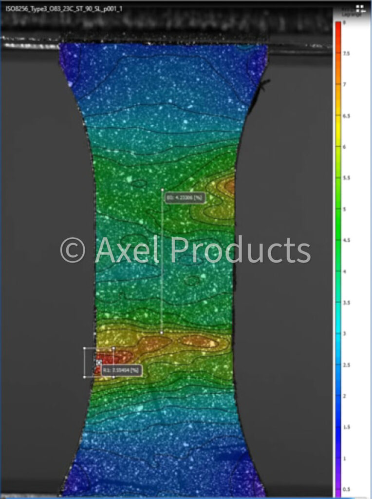
Typically, the first critical strain measurement occurs at very low strains where the initial material stiffness (modulus of elasticity) will be determined. High resolution optical extensometers using dot tracking or digital image correlation (DIC) techniques are used to measure strains at Axel.
Tensile Specimen DIC Strain Field Near Failure
Very Stretchy Plastic
Tensile Test with Axial Strain and Full Field Strain Measurement
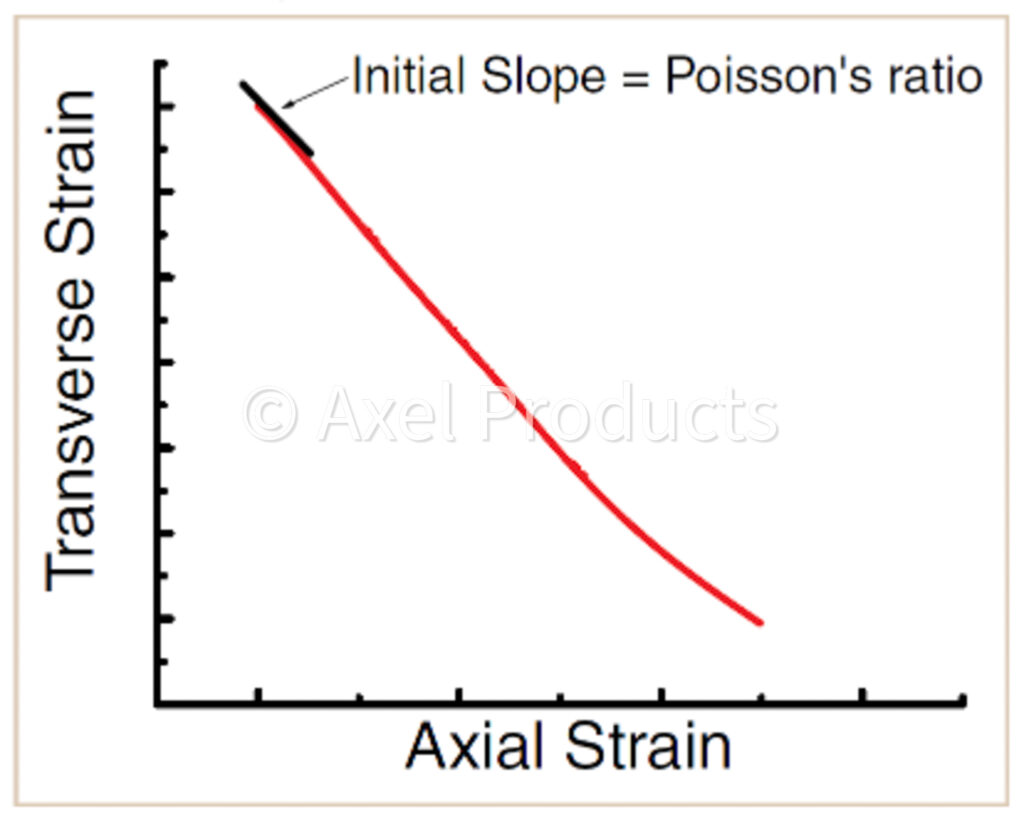
Transverse strain is sometimes measured in the modulus region in combination with axial strain such that the ratio of transverse strain to axial strain may be determined. This slope is the Poisson’s ratio and is a measure of material compressibility. This is one simple measurement that may come out of full field DIC strain measuring.
DIC Strain Measuring on the Front Face and Side Face
Compression
The compression state in plastics is naturally of great interest because plastics experience compression in service. Plastics are often injection molded and thin-walled structures are common.
To make matters difficult, the structural properties in a sheet of plastic are often different in the plane of the sheet than they are perpendicular to the plane of the sheet. Typically, the tensile, shear and compression properties in the plane of the sheet are more of interest. Measuring tensile properties in-plane is straightforward. Measuring compression in-plane requires bulky guiding fixtures to compel a thin-walled structure to load in compression without buckling.
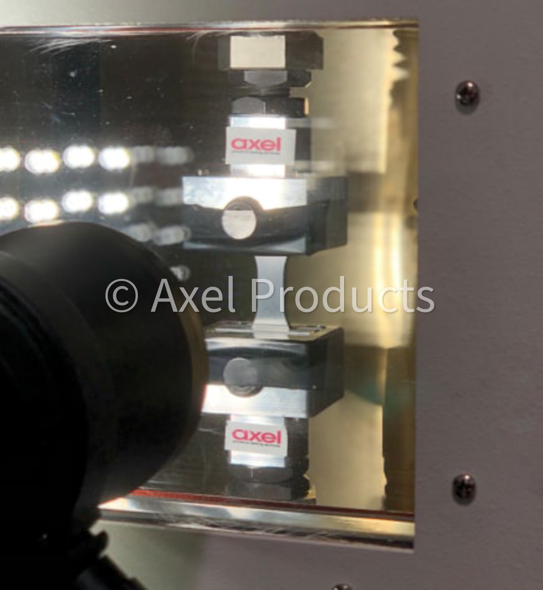
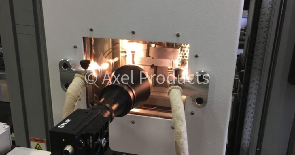
The in-plane compression experiment performed at Axel typically uses the Wyoming Combined Loading Compression Test Fixtures (ASTM D6641) modified for use with optical (DIC) strain measuring.
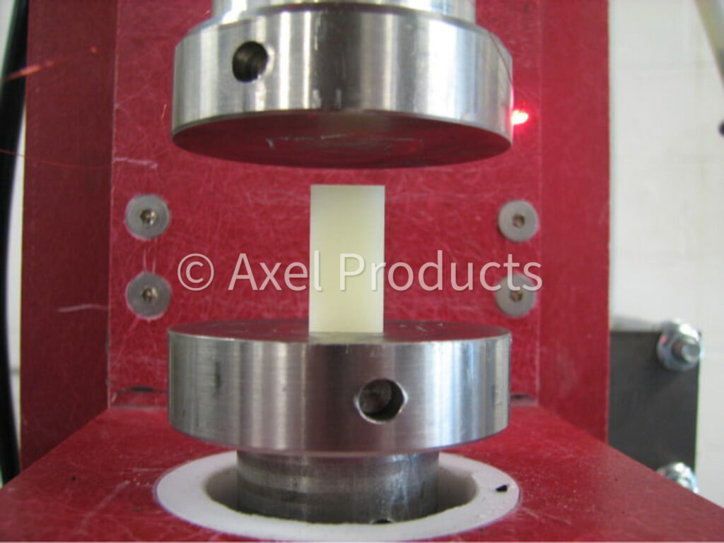
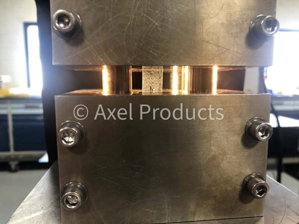
Out of plane compression tests may also be performed but the results may not match well with tensile data. The experiment is generally performed by placing a cylinder of the subject material between two flat platens and compressing it. The initial stiffness and sometimes a yielding point may be derived from the resulting stress strain curve. Direct measurement of strain at the platens is usually required.
Tensile Tester with Chamber and Optical Setup for In-Plane Compression Testing
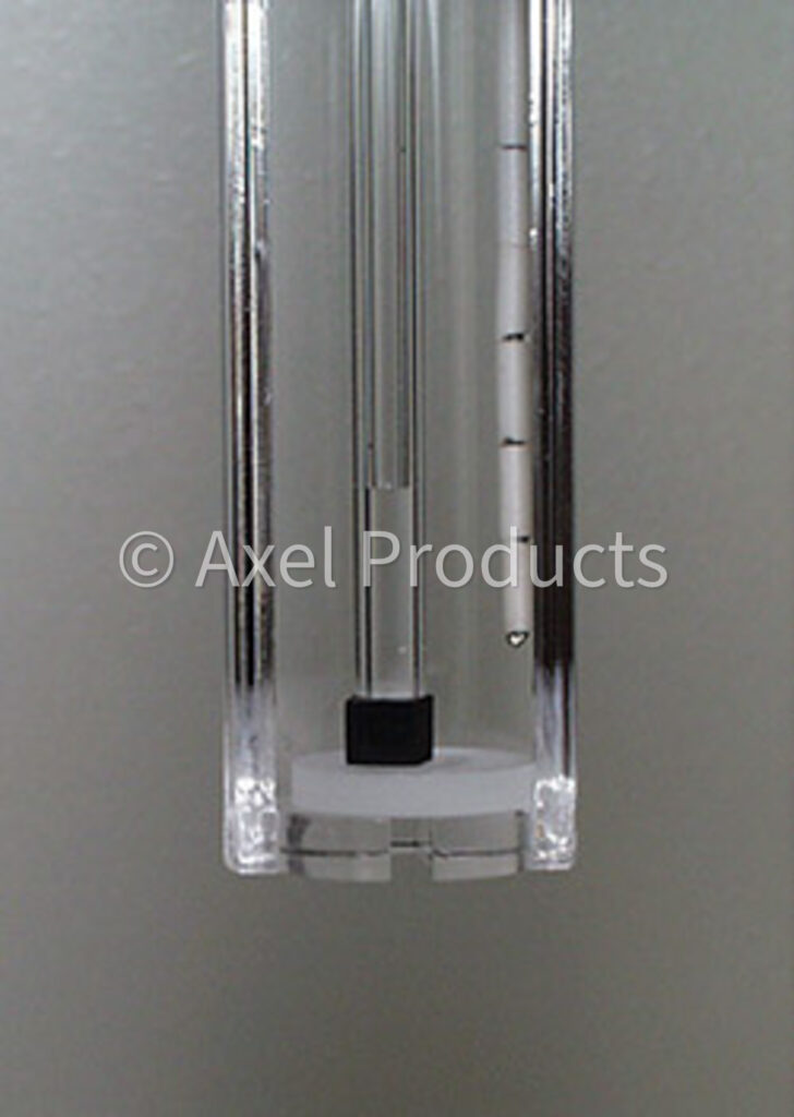
Simple Prism Compression Experiment
Fixture for In-Plane Compression Testing with DIC Speckled Specimen
Shear Measurement
The shear state of strain can be an important addition to the fitting of a material model.
The shear experiment can provide meaningful data across a wide range of material stiffnesses and a broad strain range.
Iosipescu Shear Test with DIC (ASTM D 5379)
Bend Tests
The bend test is a classic plastics experiment.
There is a wealth of data generated using this test. However, the value of the bend test for generating data for the calibration of material constitutive models is low because it is hard to determine the state of strain in the material. The bend specimen bends about a neutral axis but the location of that axis is unknown and the shape of the experiment under test is also unknown. The bend test, however, can be a useful experiment to verify the performance of a material model that is calibrated based on other states of strain.
Bend Test
Thermal Expansion
Plastics expand or contract with changes in temperature.
Plastic may also expand far more than surrounding steel parts. Thermal expansion is often given as a simple coefficient of thermal expansion (CTE) and for small temperature changes, this coefficient is a reasonable predictor of the change in part shape.
For large temperature changes, the complete thermal expansion curve over the actual range of temperatures should be considered because the thermal expansion may not be linear over the larger range.